Follow an electromagnetic pulse
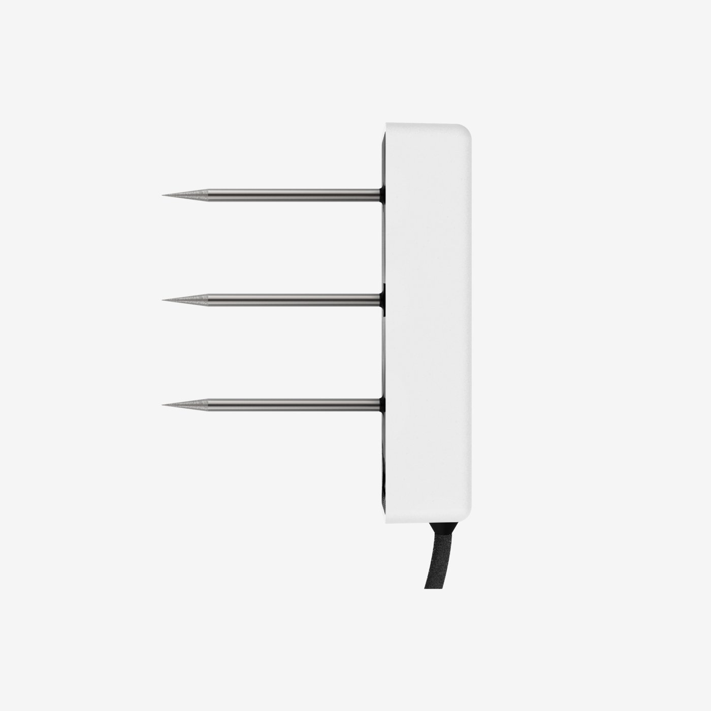
Time domain reflectometry, or TDR, sends a fast electromagnetic signal along a transmission path and interprets its travel and reflections. In soil applications, probe rods form part of that path, with soil surrounding them influencing signal propagation. The resulting travel time can be related to apparent dielectric permittivity and then converted into an estimate of volumetric water content. Water has a strong dielectric response compared with air and many soil solids under relevant measurement conditions. As water content changes, the signal response changes too. The conversion requires a known probe geometry and an appropriate calibration, rather than a direct count of water molecules.
Understand the measurement path
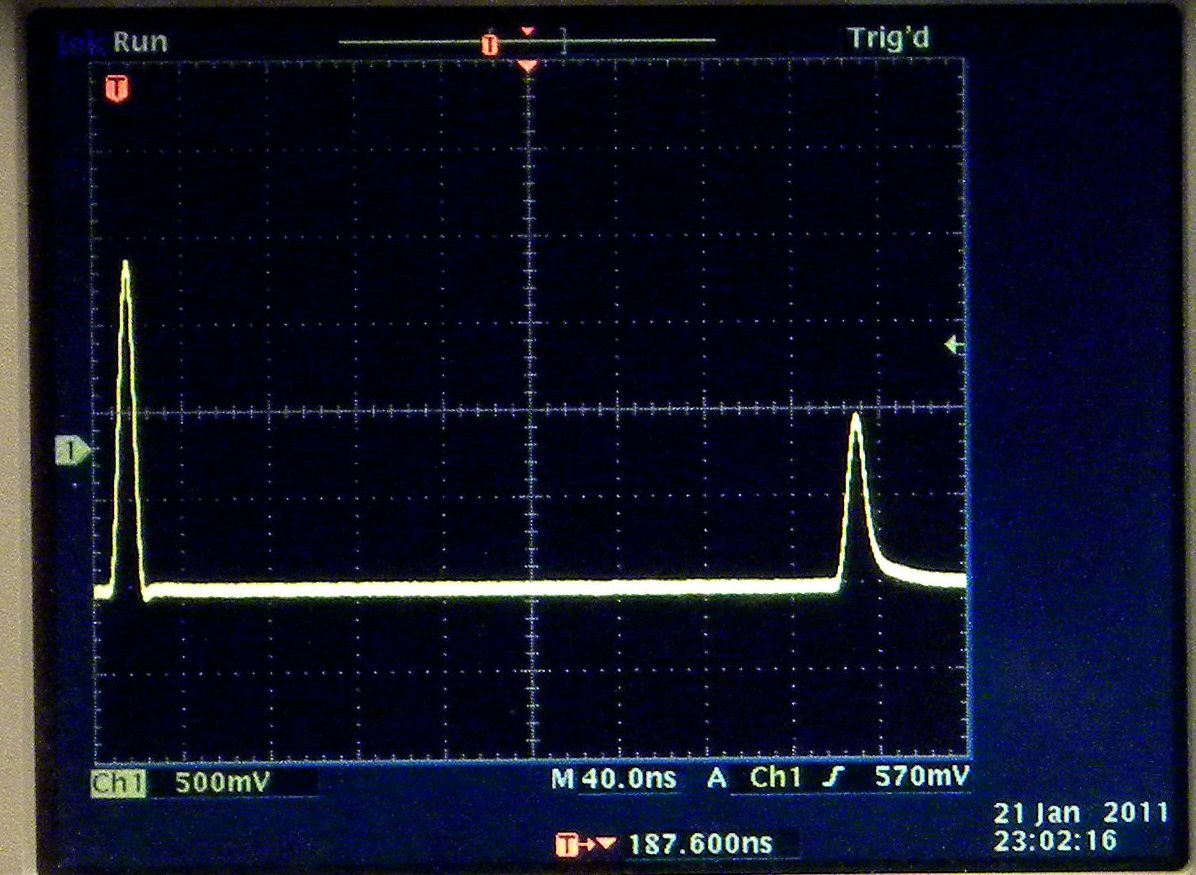
The instrument identifies features in a recorded waveform to estimate travel time along a known probe length. Connections, cable sections and the probe entrance can also create reflections. Good waveform interpretation distinguishes the relevant start and end features from those other responses. Some systems expose the waveform to the operator; others report a processed result. Ask what diagnostic information is available when readings become inconsistent. The cable waveform illustrates reflected signal features; soil measurements also require a calibrated probe geometry. Soil instruments include probe design and processing choices that determine which portion of the response produces the measurement.
Install rods with continuous soil contact
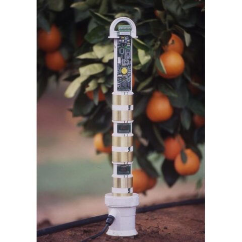
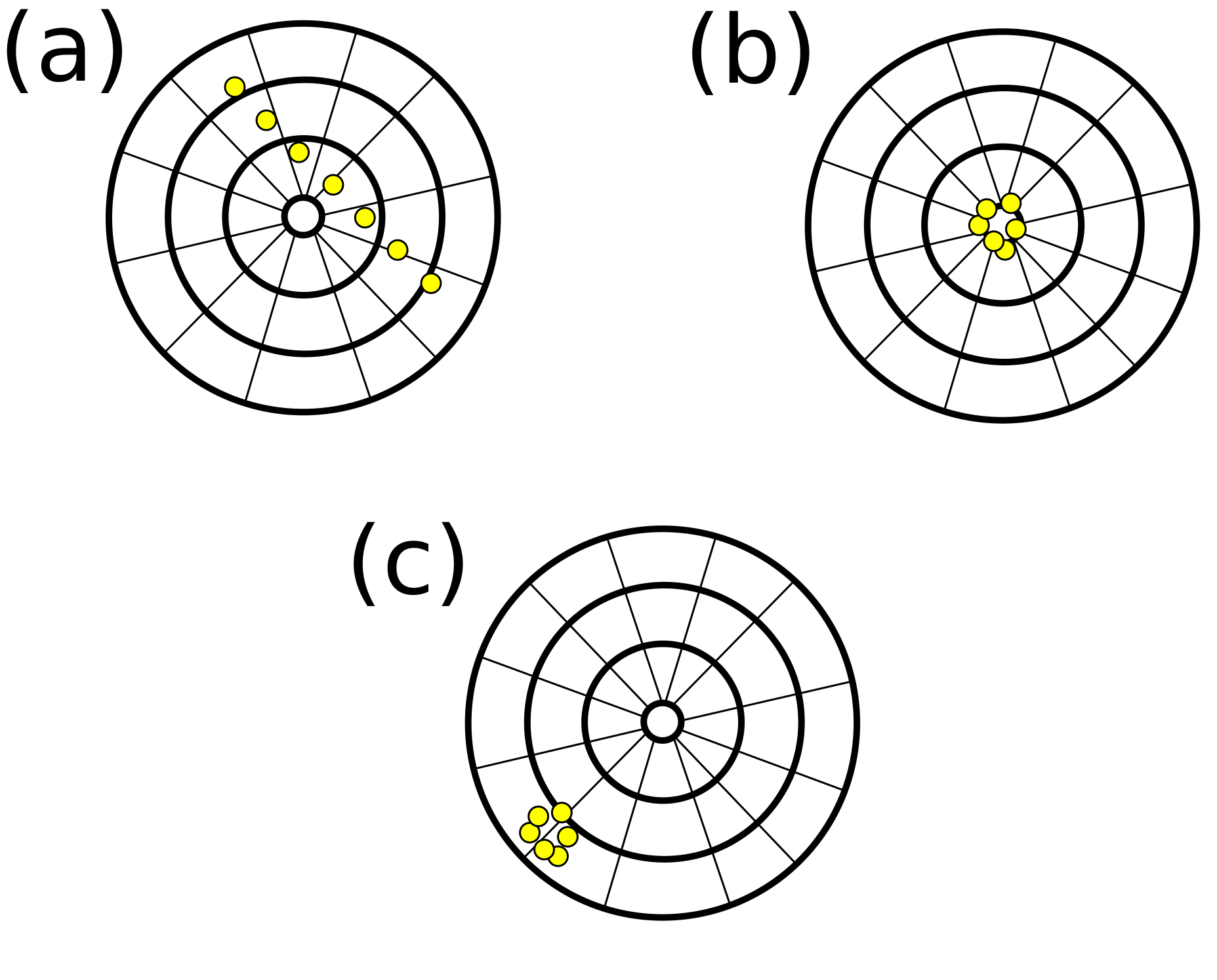
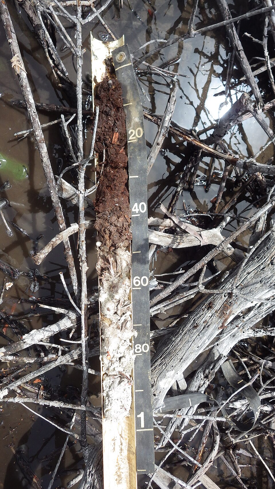
A probe measures soil in the region influenced by its electromagnetic field. That volume is limited and depends on geometry; it is not a whole-field average. Gaps around the rods introduce air with a different dielectric response, while compaction changes the material around the measurement path. Stones, roots and strongly layered soil can complicate installation. Follow the manufacturer’s procedure for insertion, hole preparation and cable routing. Record rod orientation and depth, especially when a probe crosses a horizon boundary. Consult the soil horizons guide before deciding whether one measurement should span several layers or represent a particular layer.
Check salinity and signal quality
Electrical losses can attenuate the pulse and make the end reflection harder to identify. Salinity, clay characteristics and probe length can influence this behaviour. The conductivity level at which a reading becomes unreliable depends on the particular instrument and conditions; one published threshold should not be applied to all TDR systems. Temperature and material composition can also affect the dielectric relationship used for water content. Check the documented conductivity and temperature ranges, along with procedures for recognising a poor waveform. Our permittivity guide explains why electrical storage and losses both matter to electronic moisture measurement.
Verify the water-content conversion
An empirical relationship converts the measured dielectric response into volumetric water content. General equations can work well in the soils for which they were developed, but unusual mineralogy, organic soils or growing media may need separate validation. Confirm the calibration applied by the logger or instrument, including any user-entered coefficients. Check whether reported values are raw travel time, apparent permittivity or already converted moisture content. Avoid converting the same value twice. Independent water-content samples across the working range can establish whether a local adjustment is needed. See sensor calibration for the sampling and bulk-density considerations.
Compare the complete TDR installation
TDR is a measurement method, not a guarantee of a particular communication system or maintenance requirement. Compare sensing volume, depth options, power consumption, logger compatibility and data access for the exact model. A technically capable probe will be less useful if the operator cannot retrieve the readings in time to irrigate. Consider whether waveform access is necessary for your field team and who will interpret anomalies. Compare TDR with frequency domain methods using documented performance in relevant soils. The useful choice is the instrument and installation that produces trustworthy, actionable measurements for the site.
Common questions
Does TDR eliminate the need for calibration checks?
No. The travel-time conversion, soil composition and installation still matter. Validate the applicable equation and inspect signal quality where diagnostics are available.
What should I record when comparing readings?
Keep the date, sensor model, depth, location, measurement units and calibration with the reading. Record irrigation and sampling methods where relevant so that later comparisons describe the same quantity and field conditions.
Apply this to your monitoring plan
Travel-time methods and depth layouts answer different questions.